China Best Transformer Fuse Types for Global Buyers?
Choosing the right transformer fuse is a practical reliability decision, not a catalog exercise. The Fuse Of Transformer must match the system voltage, available fault current, transformer inrush, and protection coordination. A fuse that interrupts faults quickly can still cause avoidable outages if its rating or operating curve is poorly selected. Small parts matter.
The market context is changing. The International Energy Agency’s 2023 report, Electricity Grids and Secure Energy Transitions, says annual grid investment must exceed $600 billion by 2030, more than double recent levels. More grid equipment means greater pressure to specify protection devices carefully and secure dependable replacements. Yet the report does not identify one best fuse type for every transformer; site conditions still decide.
Global buyers commonly compare expulsion or dropout fuses, current-limiting fuses, and backup combinations. Expulsion designs are often considered for outdoor distribution applications, while current-limiting units can restrict fault energy in suitable installations. These are starting points, not universal rules. IEC 60282-1 provides requirements for high-voltage current-limiting fuses, but buyers should confirm the applicable standard and local utility requirements for each project. Check rated voltage, interrupting capacity, load current, mounting arrangement, and coordination with upstream and downstream protection. Ask suppliers for test documentation and clear operating data, not just a product brochure. I have seen comparisons become too focused on purchase price; that is an easy mistake. A lower initial cost may not reflect replacement access, service conditions, or the consequences of an unnecessary outage. This guide compares the main transformer fuse types and the details buyers should verify before selecting one.
Transformer Fuse Fundamentals: IEC 60282-1 Covers AC Systems Above 1 kV
For global buyers, a transformer fuse is not just a tube with a current rating. IEC 60282-1 covers high-voltage current-limiting fuses for AC systems above 1 kV. It sets requirements and test methods that help buyers compare rated voltage, current, and breaking performance. A 12 kV installation, for example, needs a fuse rated for the system voltage and the available fault current—not merely a familiar ampere value. Small details matter.
Transformer protection also depends on coordination. A fuse must tolerate the transformer’s magnetizing inrush when it is energized, yet interrupt faults within its rated capability. Engineers compare time-current characteristics with transformer damage limits and upstream protection. They also check installation conditions, such as enclosure temperature and the fuse’s mounting arrangement.
IEC 60282-1 does not replace that system study, and it does not cover every fuse construction; expulsion-type fuses are addressed by a separate IEC standard. One detail is easy to miss: a fuse that passes a standard test may still be a poor fit for a particular network. Real fault-current data and protection curves are essential.
The paperwork can look complete, while coordination remains uncertain. That deserves a second look.
Main Types: Expulsion, Current-Limiting, and Dropout Fuses
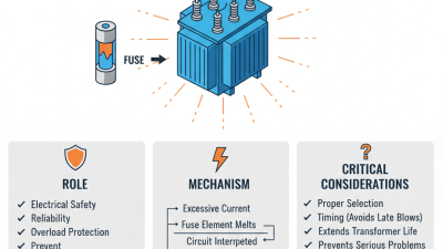
Expulsion fuses are common on distribution transformers because they clear faults through an arc-extinguishing tube. When the fuse link melts, gases help interrupt the arc and may produce a visible discharge. They are practical for many outdoor applications, but their performance depends on the fuse rating, available fault current, and installation conditions. Not a universal choice.
Current-limiting fuses act quickly and restrict the peak current passing through a fault. This can reduce thermal and mechanical stress on transformer windings. Buyers should check the fuse’s voltage and interrupting ratings, along with its time-current curve. Coordination with upstream and downstream protection matters. A current-limiting fuse may be used alone or paired with another protective device, depending on its design and intended range.
Dropout fuses are recognized by their hinged carrier, which falls open after the fuse link operates. This gives crews a visible indication that the circuit has opened. In many installations, the fuse link itself works by expulsion, so “dropout” describes the mounting and opening arrangement more than a separate interruption principle. That distinction is easy to miss. Compare transformer load, fault levels, and protection curves before choosing; a tidy product label cannot replace application data.
Fuse Selection: Match Voltage, kVA, and Inrush Current to Ratings
China Best Transformer Fuse Types for Global Buyers?
Fuse selection should start with transformer voltage and kVA, not a catalog shortcut. For three-phase units, estimate full-load current as kVA × 1,000 ÷ (1.732 × line voltage). A 500 kVA, 11 kV transformer draws about 26 A at full load. Yet its fuse must also ride through magnetizing inrush. Utility application guides commonly use 8–12 times rated current as an initial inrush screening range; actual peaks depend on residual flux, switching angle, and system impedance. Treat that range as a check, not a final rating. IEEE C37.48.1 provides application guidance for high-voltage current-limiting fuses, while IEC 60282-1 covers their requirements and tests.
Compare the fuse’s time-current curve with the transformer’s inrush and damage limits. Check minimum-melt and total-clearing curves, available fault current, and upstream and downstream coordination. A fuse that is too small may open during energization; one that is too large may not protect the transformer adequately. This is where a neat kVA table can mislead. Confirm the actual voltage class, grounding arrangement, and manufacturer’s transformer data before specifying a rating.
Tips: Record kVA, primary voltage, full-load current, and expected inrush on one worksheet. Ask the utility for fault-current data, then verify coordination using published curves. If no inrush data is available, flag the assumption rather than treating it as measured fact.
Three-Phase Transformer Full-Load Current Reference
Calculation and selection note: Three-phase full-load current is calculated as I = kVA × 1,000 ÷ (√3 × line-to-line voltage). These values are transformer currents, not fuse ratings. Fuse sizing must also account for the applicable electrical code, transformer nameplate data, system grounding, conductor protection, available fault current, and coordination requirements.
HV and LV Standards: IEC 60269 Covers Up to 1,000 V AC
For transformer protection, the voltage boundary matters. IEC 60269 covers low-voltage fuse-links rated up to 1,000 V AC. It gives buyers a shared basis for checking characteristics such as rated current, breaking capacity, and operating behavior. A fuse marked for a suitable current is not automatically suitable for every transformer.
The application details matter. A transformer draws a brief inrush current when energized, while a downstream fault may demand rapid interruption. Buyers should compare time-current curves with transformer data and the protection devices on both sides. Check the system voltage, prospective short-circuit current, enclosure conditions, and installation requirements. Small details count.
HV is different. IEC 60269’s 1,000 V AC scope should not be treated as a specification for high-voltage fuse links; those require the relevant standards and system-specific review. Procurement documents can still be imperfect, and ratings may be copied without context. Ask for test documentation and confirm the exact fuse class and intended duty before approval. A careful review takes time, but a mismatched fuse can disrupt protection coordination.
Global Verification: IEEE C37.41 Specifies High-Voltage Fuse Test Requirements
Transformer fuse choices commonly include current-limiting and expulsion designs, but the correct type depends on the transformer’s voltage, fault level, and protection scheme. Current-limiting fuses restrict peak fault current; expulsion fuses interrupt faults through an arc-extinguishing process. Small details matter. Check the fuse’s rated voltage and interrupting capacity against the installation, not just its product label.
IEEE C37.41 specifies design tests for high-voltage fuses and related accessories, including dielectric, temperature-rise, and interrupting tests. These tests help buyers compare performance under defined conditions. They do not, by themselves, confirm that a fuse will coordinate correctly with every transformer or upstream device. The International Energy Agency’s Electricity Grids and Secure Energy Transitions (2023) says annual grid investment must rise from about USD 300 billion to more than USD 600 billion by 2030. More equipment is entering service, so consistent verification matters. Still, paperwork can be incomplete; request test evidence for the exact fuse type and rating.
Tips: Ask for the applicable IEEE C37.41 edition, test reports, and time-current data. Confirm coordination with the transformer’s protection settings. Keep a little skepticism: similar-looking ratings may conceal important differences.