As electricity networks expand, transient overvoltage protection becomes a practical reliability decision, not a catalogue exercise. The IEA’s Electricity 2024 report forecasts global electricity demand growth of more than 3% annually through 2026. That growth will pressure transmission, distribution, renewable, and industrial assets. Every exposed transformer, cable termination, and substation entrance deserves a careful protection review.
A Polymeric Surge Arrester can offer valuable advantages in these environments. Its lightweight housing simplifies installation, while silicone rubber can improve pollution performance and reduce shattering risks. Yet housing material alone does not prove protection quality. The arrester’s continuous operating voltage, residual voltage, energy capability, thermal stability, creepage distance, and sealing design must match the system.
Small details matter.
IEC 60099-4 establishes performance requirements and test principles for metal-oxide surge arresters used on alternating-current systems. IEEE Std C62.11-2020 provides additional guidance for metal-oxide arresters without gaps. These standards support disciplined comparison, but field conditions still complicate selection. Salt deposits, dust, humidity, temporary overvoltages, lightning density, and switching events can produce different stresses at the same nominal voltage.
The IEA’s Electricity Grids and Secure Energy Transitions report warns that grid investment and modernization must accelerate worldwide. More connected equipment means more opportunities for transient damage. This guide explains how to choose a Polymeric Surge Arrester in 2026 using technical ratings, installation evidence, supplier testing, and lifecycle considerations. No selection is perfect. A specification that looks convincing on paper may still fail when grounding, coordination, or maintenance assumptions remain unverified.
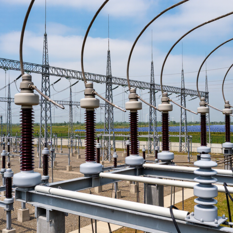
How to Choose a Polymeric Surge Arrester in 2026?
What a Polymeric Surge Arrester Is and How It Works
A polymeric surge arrester protects electrical equipment from sudden overvoltages caused by lightning or switching events. Its core usually contains zinc oxide metal-oxide blocks. Under normal voltage, these blocks conduct only a tiny leakage current. During a surge, their resistance drops sharply, creating a controlled path to ground. Excess energy is discharged safely. The arrester then returns to its insulating state.
The polymeric housing adds practical protection. It is lightweight, sealed, and resistant to moisture, but performance still depends on installation conditions. Check the system voltage, continuous operating voltage, discharge current, energy capability, altitude, and pollution level. Creepage distance matters near coastal or industrial sites. A poorly matched arrester can fail quietly before anyone notices. That is an uncomfortable point.
Tips: Compare certified test reports, not only catalog values. Inspect seals, terminals, and grounding connections during maintenance. Confirm that the arrester’s thermal stability suits the network. Also review the expected fault current and temporary overvoltage duration. Field records can reveal more than a perfect specification sheet. If the environment is unusually harsh, ask for independent verification. This step may seem excessive, yet skipping it can make a reliable design less reliable.
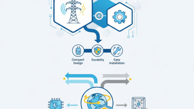
Polymer-housed surge arresters use metal-oxide varistors to conduct surge current to ground and limit the voltage reaching protected equipment. The chart compares the standardized impulse-waveform timings commonly used when evaluating arrester performance: an 8/20 μs current impulse has an 8 μs nominal front time and reaches half of its peak value after 20 μs, while a 10/350 μs lightning-current impulse has a 10 μs front time and a 350 μs time to half value. When selecting an arrester, also verify continuous operating voltage, temporary overvoltage withstand, nominal discharge current, energy capability, pollution level, and mechanical performance of the polymer housing.
Choosing a polymeric surge arrester starts with voltage, but voltage alone can mislead. Check the system’s highest operating voltage and select the correct maximum continuous operating voltage, or MCOV. Then examine temporary overvoltages caused by faults, switching, or poor grounding. A neat voltage match can still be wrong. The arrester must also suit the system connection, including grounded, ungrounded, or resistance-grounded networks. Review expected surge energy, discharge current, insulation coordination, and the equipment’s impulse withstand level. Technical records and certified test results matter more than attractive catalog numbers.
Environmental conditions can quietly shorten service life. Measure altitude, humidity, salt exposure, industrial pollution, dust, and ultraviolet radiation. Coastal substations may need longer creepage distances and stronger sealing. In dusty areas, inspect the housing profile and washability. Consider wind, ice, vibration, and the available installation space. Polymer housings are light and resistant to shattering, yet incorrect mounting can still create mechanical stress. Field inspections often reveal this overlooked detail.
Tips: Compare MCOV with real system data, not nominal voltage. Confirm grounding assumptions with the protection engineer. Check leakage-current monitoring, clearances, and replacement access. If site information is incomplete, pause the selection. Guessing is expensive. Revisit the decision after reviewing fault studies, local weather records, and the arrester’s verified test documentation.
How to Choose a Polymeric Surge Arrester in 2026?
Comparing arrester ratings requires more than checking rated voltage. Start with the system’s maximum continuous operating voltage, or MCOV. The arrester’s MCOV must tolerate normal voltage without unnecessary leakage current. Then review temporary overvoltage withstand, especially on systems with earth faults or switching events. Rated voltage and MCOV are related, but they are not interchangeable.
Protective performance is shown through residual voltage at a defined impulse current. Compare values under the same waveform, such as an 8/20 microsecond impulse at 5 kA or 10 kA. A lower residual voltage usually gives better equipment protection. However, coordination still matters. The arrester’s protection level should remain below the equipment insulation withstand level, with a practical safety margin. Check steep-front and switching impulse data too. One table may hide important differences.
Tips: Compare identical test conditions. Check energy capability and line discharge class. Inspect creepage distance, sealing, and polymer housing quality. Confirm altitude and pollution assumptions. Field experience also shows that cable length can change actual protection. I have seen selections based only on catalog voltage. That shortcut looked reasonable, but it ignored temporary overvoltage and installation distance. Recheck the complete system. Numbers need context.
| Comparison Dimension | What to Check | Typical Values or Requirements | Why It Matters |
|---|---|---|---|
| System voltage | Maximum continuous operating voltage of the network | Select the arrester for the applicable system line-to-line voltage and grounding arrangement; common medium-voltage systems include 6.6, 11, 13.8, 22, 24.9 and 33 kV | The arrester must withstand normal operating voltage without excessive leakage current or thermal instability. |
| MCOV / Uc | Maximum continuous operating voltage | Choose an MCOV at or above the highest continuous phase-to-earth voltage, including expected voltage variation; commonly specified values include 4.8, 7.65, 8.4, 12.7, 15.3, 17 and 24.4 kV | A low MCOV can cause overheating and premature failure, while an unnecessarily high MCOV can reduce protection margin. |
| Rated voltage / Ur | Temporary overvoltage withstand capability | Verify the manufacturer-declared temporary overvoltage curve for the expected duration, grounding method and fault-clearing time | Temporary earth faults can raise the voltage on healthy phases above normal operating levels. |
| Nominal discharge current | Standard current used for classification and residual-voltage testing | Distribution arresters commonly use an 8/20 μs nominal discharge current of 5 kA or 10 kA; higher-current classes are used where exposure is greater | A higher nominal current class generally provides greater energy and surge-current capability, but does not automatically mean lower protective voltage. |
| Line-discharge class | Energy capability for repeated or high-energy impulses | For IEC 60099-4 high-voltage applications, line-discharge classes are designated from Class 1 through Class 5; select according to network exposure and required energy absorption | The class indicates energy-handling capability and is especially important for transmission, transformer and high-fault-level applications. |
| Residual voltage / protective level | Voltage remaining across the arrester during a specified impulse current | Compare residual-voltage values at the same current waveform and magnitude, such as 1.5 kA, 5 kA or 10 kA at 8/20 μs | Lower residual voltage normally provides better equipment protection, provided the arrester still has adequate MCOV and energy capability. |
| Protection ratio | Relationship between protective level and MCOV or equipment insulation level | Use the complete manufacturer test data rather than comparing a ratio calculated from different test currents or voltage bases | A consistent comparison prevents misleading conclusions about arrester performance. |
| Equipment insulation level | Basic insulation level and power-frequency withstand level of the protected equipment | For medium-voltage equipment, common lightning impulse withstand levels include approximately 60, 75, 95 and 125 kV, depending on the rated voltage and insulation coordination | The arrester protective level must remain sufficiently below the equipment withstand level after considering lead voltage. |
| Lead length and installation | Phase and earth connection length, routing and bonding | Keep connections short, direct and low-inductance; avoid unnecessary bends and connect the earth lead to the same effective grounding point as the protected equipment | Inductive voltage developed in long leads can substantially increase the voltage seen by the equipment. |
| Short-circuit capability | Pressure-relief and fault-current withstand rating | Confirm the arrester short-circuit rating is equal to or greater than the available prospective fault current at the installation point | This supports safe failure behavior if the arrester is damaged or reaches the end of its service life. |
| Housing material and creepage | Silicone-rubber housing, shed profile and creepage distance | Specify pollution severity and required creepage in accordance with the applicable insulation-coordination standard; silicone housings are commonly selected for hydrophobicity and contamination performance | Housing design affects outdoor insulation, contamination withstand, moisture resistance and mechanical durability. |
| Environmental conditions | Altitude, temperature, humidity, pollution, ultraviolet exposure and wind | Check the declared operating range; common outdoor designs are specified around −40 °C to +40 °C, with separate verification required for severe conditions or high altitude | Environmental derating and contamination can reduce insulation performance and service life. |
| Standards and type tests | Applicable product and application standards | Request evidence of compliance with IEC 60099-4 or IEEE C62.11, as applicable, including duty, aging, moisture, high-current and short-circuit tests | Standardized testing makes ratings and protective-performance data more comparable. |
Note: Values shown are representative selection ranges, not a substitute for a system-specific insulation-coordination study. Final selection should use the network voltage, grounding method, temporary overvoltage duration, lightning exposure, available fault current, equipment insulation level and installation geometry.
How to Choose a Polymeric Surge Arrester in 2026?
A polymeric surge arrester should survive more than a laboratory impulse. Its housing faces sunlight, rain, salt, dust, and sudden temperature changes. Silicone rubber often maintains useful hydrophobicity, while EPDM may require different protection against aging. Material choice must match the installation environment, not just the purchase price. Check verified test evidence for leakage current, tracking resistance, UV exposure, and thermal cycling.
Construction details reveal practical quality. Examine shed spacing, bonding between the housing and core, sealing around metal fittings, and the pressure-relief path. A smooth interface reduces moisture entry. Secure end fittings prevent movement during short-circuit events. In coastal service, inspect exposed hardware for corrosion compatibility. Small gaps matter.
Field experience can be less tidy. A clean surface does not prove an intact internal seal. I have seen units pass a visual inspection while showing abnormal leakage current later. Request routine and design-test records aligned with applicable standards, such as IEC 60099-4, and confirm who performed the testing. Review operating temperature, pollution level, altitude, and expected fault current before approval. Do not accept vague claims like “maintenance-free” without service data. That phrase deserves skepticism. Check sample inspection photos, installation torque requirements, and warranty conditions. A durable housing is valuable, but the complete arrester design determines whether it remains dependable after years outdoors.
Selecting the right polymeric surge arrester starts with the system, not the product catalogue. Confirm the highest continuous operating voltage, temporary overvoltage conditions, insulation level, and expected lightning exposure. The arrester’s MCOV must suit the network’s real voltage, including grounding behavior. Check the latest applicable requirements, such as IEC 60099-4, and verify test evidence from a qualified laboratory. Pollution, altitude, coastal salt, and mechanical loads also affect the choice. A compact arrester may look suitable, yet its creepage distance could be inadequate.
Installation quality matters just as much. Mount the arrester close to the protected transformer, cable termination, or equipment terminal. Keep phase and ground connections short, straight, and firmly secured. Long bends add inductive voltage during a surge. Follow the manufacturer’s torque values and clearance instructions. Inspect the grounding path, because a low-resistance earth connection does not always mean a low-inductance path. This detail is often underestimated.
Tips: Record the arrester rating, location, installation date, and test documents. During maintenance, look for cracks, tracking, contamination, loose hardware, and unusual heating. Compare inspection photos over time. Leakage-current readings can help, but they need proper instruments and weather context. Do not rely on one measurement. A visual check may miss internal aging, while a clean surface may hide a serious problem. Maintenance intervals should reflect local storms and pollution, not just a calendar. A practical plan should be reviewed after every major fault or network change.