Why Choose the Right Lightning Arrester?
A storm can turn a quiet afternoon into a test of every electrical connection in a building. A sharp flash, a nearby strike, and a sudden surge can damage equipment or interrupt essential operations. The right Lightning Arrester helps limit that risk by providing a controlled path for surge energy to reach earth. But choosing one is not a matter of picking the largest model on a shelf.
Benjamin Franklin’s work helped establish the value of lightning protection. His familiar warning, “An ounce of prevention is worth a pound of cure,” fits the decision well. It is a useful reminder, not a substitute for engineering. The arrester must match the system voltage, expected exposure, installation environment, and equipment being protected. A unit suited to one site may be inadequate or poorly matched at another.
Details matter. Consider cable length, earthing connections, enclosure conditions, and the distance between the arrester and sensitive equipment. A loose connection or unsuitable rating can undermine an otherwise careful design. Yet product specifications alone do not tell the whole story. Site assessment and qualified installation matter, too.
There is no magic box. Even a well-selected Lightning Arrester cannot remove every hazard or replace routine inspection. That deserves a second look, especially where systems change over time. This guide explores the practical factors behind selection, helping readers ask sharper questions before they buy or install protection.
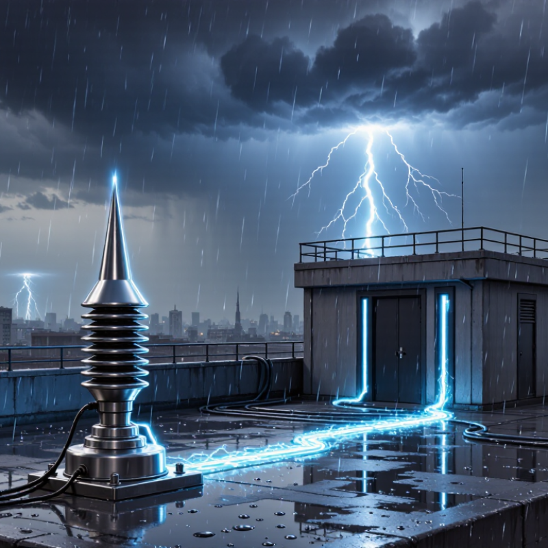
A lightning arrester helps limit sudden voltage spikes before they damage insulation, wiring, or connected equipment. The most obvious threat is lightning: a nearby strike can induce a surge in overhead lines, even without hitting a building directly. A strike to a power line may also send a sharp transient toward service equipment.
The spike is brief. Yet it can puncture insulation or disrupt sensitive controls. Lightning is not the only source. Utility switching, capacitor-bank operations, and the starting or stopping of large motors can create switching surges. These events may be smaller than lightning surges, but repeated spikes can still stress equipment over time.
A properly selected arrester provides a low-impedance path for surge current to earth and helps keep voltage at safer levels. Grounding matters. Long leads or poor connections can reduce protection, and an arrester cannot prevent every failure or correct sustained overvoltage. It is worth checking whether the arrester’s rating, location, and grounding match the system. That detail is easy to overlook, and it deserves a second look.
Choosing a lightning arrester starts with the voltage it will actually see, not just the system’s nameplate rating. MCOV, also called Uc, is the maximum voltage the arrester can withstand continuously across its terminals. It must suit the highest expected continuous operating voltage at the installation point.
System grounding changes that voltage. On a solidly grounded system, phase-to-ground voltage is usually lower than phase-to-phase voltage. But during a ground fault, an ungrounded or impedance-grounded system can expose healthy phases to a much higher voltage. Small details matter. Check the system configuration, operating limits, and possible temporary overvoltages before choosing an MCOV. A voltage table alone can mislead; I’ve seen how easily nominal values hide those conditions.
MCOV is only one part of the rating. The arrester’s protection level must also coordinate with the equipment’s insulation withstand, with practical allowance for cable length and installation layout. A long lead can add voltage at the protected equipment. That gap matters. Review the manufacturer’s technical data and the project’s applicable engineering requirements, then confirm the selection with a qualified electrical professional. If the available fault or grounding information is uncertain, pause and verify it rather than sizing from the system label alone.
Why Choose the Right Lightning Arrester?
Which Discharge Rating Fits? Typical Tests Use an 8/20 μs Waveform
An 8/20 μs current impulse rises to its peak in 8 microseconds and falls to half that value in 20. It gives engineers a repeatable way to compare an arrester’s discharge behavior. But the test number alone does not determine the right rating. A high peak-current value may look reassuring, yet system voltage, expected surge exposure, and protective coordination matter too. At a building entrance, for example, the arrester must limit voltage without compromising normal operation. The choice is not always tidy.
Tips: Check the product’s test conditions and rated discharge current, not just the headline figure. Compare them with the installation point and the equipment’s withstand level. Ask a qualified electrical professional to review coordination.
Also consider how often surges may occur and how much energy the arrester must handle over time. An 8/20 μs waveform represents a specific impulse test; it does not describe every real-world surge. That distinction is easy to overlook. Review the applicable technical documentation, including residual voltage and duty ratings, before specifying a device. A rating chosen only for a larger number can still leave sensitive equipment poorly protected.
| Application or SPD Type | Relevant Discharge Rating | Typical 8/20 μs Rating Examples | How to Choose | Key Test Consideration |
|---|---|---|---|---|
| Type 2 SPD at a distribution board | Nominal discharge current, In | 5 kA or 10 kA per protected mode are common product ratings. | Check the expected surge environment, installation location, system voltage, and the manufacturer’s declared protection level. | In is tested using an 8/20 μs current impulse. It indicates a declared test duty, not a guarantee against every surge. |
| Type 2 SPD where higher surge exposure is expected | Maximum discharge current, Imax | 20 kA, 40 kA, or higher per mode are examples found in product specifications. | Compare Imax alongside In, protection level, short-circuit rating, and the required coordination with upstream and downstream devices. | Imax is generally an 8/20 μs maximum-duty test value. A higher number alone does not establish better protection in every installation. |
| Type 1 SPD at a service entrance or location exposed to partial lightning current | Impulse current, Iimp | Typically specified with a 10/350 μs waveform; an 8/20 μs Imax value may also appear separately. | Select using the applicable installation standard, lightning protection design, service arrangement, and required current-sharing capability. | Do not treat an 8/20 μs rating as equivalent to Iimp. The 10/350 μs test represents a different and substantially greater charge and energy duty. |
| Type 3 SPD installed close to sensitive equipment | Combination-wave test rating and declared discharge current | Specifications may state an 8/20 μs discharge-current value; values vary by device and test configuration. | Use as coordinated downstream protection, not as a substitute for suitable upstream protection. Check the required separation or coordination conditions. | Type 3 testing commonly uses a combination-wave generator, with a 1.2/50 μs open-circuit voltage and an 8/20 μs short-circuit current. |
| Residential or light-commercial distribution board | In and Imax per mode | Example comparison: 5 kA In / 20 kA Imax versus 10 kA In / 40 kA Imax. | Use the site’s exposure assessment and applicable code requirements to choose; verify the SPD’s maximum continuous operating voltage and protection level. | Confirm whether the stated current is per mode, per pole, or for the complete device. These values are not interchangeable. |
| Industrial or higher-exposure distribution system | In, Imax, and, where required, Iimp | Higher 8/20 μs ratings may be specified, but the appropriate value depends on the system design and exposure. | Assess the incoming supply, exposure to lightning or switching surges, earthing arrangement, prospective fault current, and coordination between SPDs. | For systems requiring Type 1 protection, check the 10/350 μs Iimp rating separately from any 8/20 μs ratings. |
Note: An 8/20 μs waveform has a nominal 8 μs virtual front time and a 20 μs time to half-value. The example ratings above are representative specification values, not universal selection requirements. Always verify the applicable standard, product datasheet, system voltage, installation conditions, and coordination requirements.
Why Choose the Right Lightning Arrester?
How Does the Arrester’s Protection Level Coordinate With Equipment BIL?
An arrester should clamp surge voltage below the equipment’s Basic Insulation Level (BIL), with a practical margin after installation effects are considered. IEC 60071-1 defines standardized insulation withstand levels, while IEEE C62.22 provides application guidance for coordinating arresters and equipment insulation. Consider a hypothetical 150 kV BIL and a 120 kV arrester protective level: the nominal margin is 25%, calculated against the protective level. This is an example, not a universal selection rule. Lead length, grounding, surge current, and waveform can raise voltage at the equipment terminals. The nameplate figures alone can mislead.
Tips: Check the arrester’s residual voltage at the relevant discharge current, then include connecting-lead effects. Keep leads short and straight. Verify the actual BIL from equipment records, not a rough voltage-class assumption.
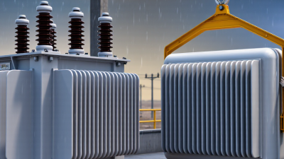
A field detail matters: a long, looping lead beside a transformer can add inductive voltage during a fast surge. IEEE C62.22’s coordination approach makes the complete installation important, not just the arrester rating. On paper, a 25% margin looks comfortable. It may not be, if the lead layout or system conditions differ from the assumptions. Review those details with the equipment withstand data before choosing an arrester.
Selecting an IEC 60099-4 arrester class starts with the site’s actual electrical and environmental stresses, not its voltage rating alone. IEC 60099-4:2014 defines five line-discharge classes, from Class 1 to Class 5, to distinguish energy-handling capability under specified test duties. Higher classes may suit demanding line-discharge conditions, but they do not automatically provide the best protection for every installation. The required continuous operating voltage, temporary overvoltages, expected surge currents, and arrester energy duty all matter.
A practical assessment should use the system’s grounding method, fault-clearing time, lightning exposure, and switching events. Check the arrester’s protective level against the insulation withstand of nearby equipment, such as a transformer terminal beside a long cable run. Then confirm that thermal recovery remains adequate after the site’s likely surge sequence. Not a catalog choice. CIGRE guidance on surge-arrester application also emphasizes matching arrester characteristics to network stresses, rather than selecting by class alone. One detail is easy to overlook: an assumed fault duration may not match real relay settings. That uncertainty deserves review before specifying a class. A site study, verified settings, and the IEC test data provide a more defensible selection.
How to read this chart: IEC 60099-4 defines line discharge classes 1 through 5. The bars show the class designations only—not energy ratings or a universal ranking of site suitability. Select an arrester based on the system voltage, continuous operating voltage, temporary overvoltages, expected discharge duty, and protective coordination. Confirm the choice against the applicable standard and the arrester’s technical data.